
Together with Mukdam Habib Shamoon Kena from Al-Jami'at Al-Technologia in Baghdad/Iraq, we developed a flexible engineering tool in Matlab that layouts toolpaths for the milling of surfaces. In four instances, the design files output by the software are processed by cnc-machines, see video recordings of the milling. The development was subject to constant revision and improvement from November 2006 to July 2007.
The software as well as the practical work supplement Mukdam Kenas thesis, which he defended at the Department of Production and Metallurgy Engineering in September 2007 and earned an excellent mark. He designed three shapes by our software. The parts were fabricated by Marian Fujara from the Institut für Produktionsmanagement, Technologie und Werkzeugmaschinen in Darmstadt/Germany, who consulted us on the practical issues. The material used is Ureol.
Subsequently, his friend Abass Maithem Jabber Al-Enzi employed the software to perform similar shapes design and analysis. His results are also compiled into a thesis, which he defended in May 2008. One shape that he designed was manufactured from a block of Cibatool at Protoshop Oy in Espoo, Finland.
The software features
The key algorithms are
| Analysis and Application of Subdivision Surfaces (Thesis) 1 |
|
4.5 MB |
| Studying Curve Interpolator for CNC System (Thesis) 2 |
|
6.2 MB |
| Toolpath Design and Milling Simulation (MATLAB) 3 |
|
300 kB |


Special thanks to Natascha Wöhlert and Markus Klinger for the logistics.
I downloaded TPM code and run it.
TPM code is great.
Student at University of Marmara
The user input to the software are
The toolpath consists either of lines parallel to one axis, or a bi-directional layout. Internally, we represent the target surface as a real-valued function f(x,y) sampled over a 2D-grid.
Based on these specifications, the software will layout a suitable path for the cutter. The underlying algorithm employs the surface normals provided by the command surfnorm, which are meaningful where the surface is smooth. To overcome the problems at sharp features, we elevate the toolpath according to its cross-section whereever necessary to avoid intrusion of the target surface.
At this point, the toolpath is represented by a very dense sequence of points in 3D. When three subsequent points are on a straight line, we remove the middle point to compress the toolpath representation.
The simulation of the milling process starts by assuming a block of material with infinite height. The simulation comprises of a loop over adjacent coordinates of the toolpath. Depending on the elevation and the length of such a segment, we generate the corresponding impression of the cutter: a bivariate function sampled over a fine grid patched with NaN away from the influence of the cutter. We store the minimum of the block and the impress as the new block of material. Because the impress and the block are not sampled over the same domain, we employ the quite efficient linear interpolation routine 'interp2'.
Aside from these central aspects, we compute the gaussian- and mean-curvature of the target surface. Also, the software notifies the user of the maximum possible ball-tip cutter radius. The toolpath is exported to a DXF file, which is compatible to the Surfcam, and AutoCAD programs. In addition, the toolpath is translated into NCC format, compatible to cnc-milling mashines with Fanuk control.
Issues to address in future versions:
The graphic below shows the conceptual design of our engineering tool.
Ein echt positiver Aspekt der
Globalisierung und des Internets!
Roman Alexander Dickmann
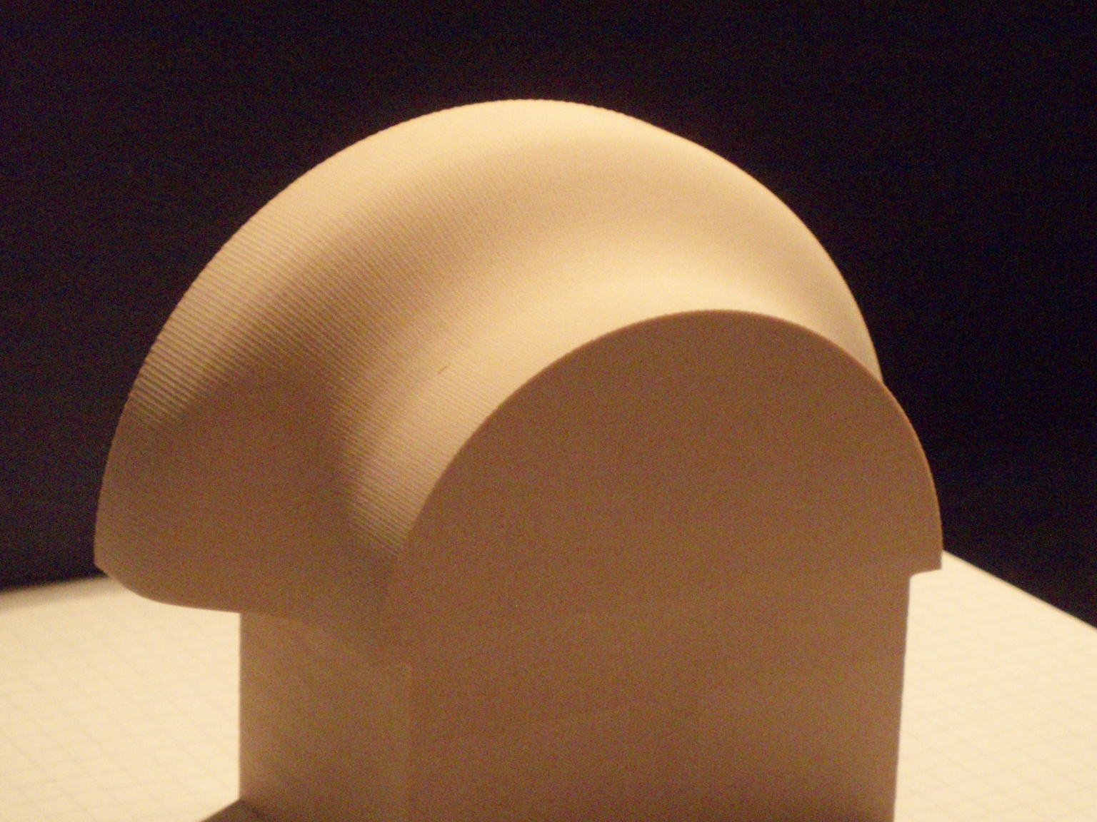
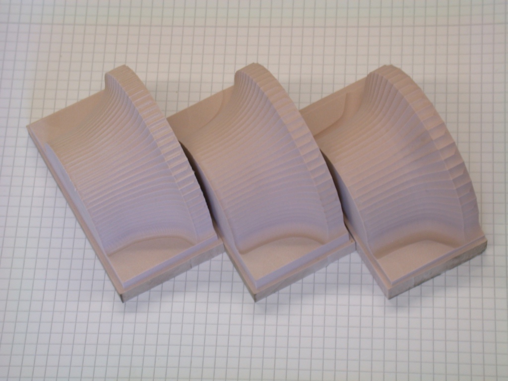
Using our software, Mukdam Kena has designed three slightly different shapes. The shapes are rotationally symmetric with cross-section based on bspline, linear- and cubic-interpolation. The layout of the toolpaths was adapted to the balltip cutters with diameters of 6, 8, and 10mm.
The actual CNC-milling was performed on a Hermle C30U dynamic machine of the Institut für Produktionsmanagement, Technologie und Werkzeugmaschinen in Darmstadt/Germany. The machine has the following characteristics:
We use the probe material Ureol for good machinability and minimal deflection. The initial blocks of Ureol have the dimensions 90x45x43 mm.
Conventionally, the finishing procedure is preceeded by a roughing procedure. By that time, our software could not produce a toolpath for roughing that was pratical. However, the material Ureol allows to repeat the toolpath for finishing several times decreasing the height a little bit each time. It turned out that a conventional roughing procedure was not obligatory. [pic]
Große Zeit ist es immer nur,
wenn's beinah schief geht,
wenn man jeden Augenblick fürchten muß:
Jetzt ist alles vorbei.
Heinrich Theodor Fontane
Abass Jabber has designed a similar shape. The toolpath is streamline. The diameter of the ball-tip cutter for the finishing process is 5 mm. Download the toolpath in dxf format.
The actual milling was performed on a Okuma VH-40-HS dynamic machine at Protoshop Oy in Espoo, Finland. The machine has the following characteristics:

We use the prototype material Cibatool for good machinability and minimal deflection.
Roughing was carried out with a 16 mm cutter in order to efficiently remove probe material that is far from the target surface. [pic]
I do not want my house to be walled in
on all sides and my windows to be stiffled.
I want all the cultures of all lands
to be blown about my house as freely as possible.
But I refuse to be blown off my feet by any.
Mohandas Karamchand Gandhi
![[pic]](milling/toolpath_milling1.jpg)
![[pic]](milling/toolpath_milling2.jpg)